Characteristics of
A Small Hand-Held Generator
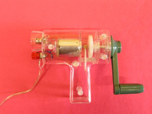
Note:
The case of this generator is made of plastic. The gears inside are made of nylon. This works well, but is definitely NOT a sturdy piece of equipment. If you try, you will be able to break it. If you break it, you will pay for a new one.
The objective of this lab is for you to observe and report on a few characteristics of this electrical generator.
Instructions:
1. Attach a Voltage-Current sensor to the USB link and then plug the USB Link into your computer.
2. When the window appears click on LAUNCH DATA STUDIO.
3. Data Studio will launch and you will see two digital displays, voltage and current. It will probably be easier to work with a graph, so drag the voltage data and drop it on the graph display and you should have a voltage-time graph.
4. Click “start” and “stop” to begin and end runs. Click Experiment/Delete All Data Runs to clean up the display when it gets too “busy”.
5. Attach the voltage probe wires from the Voltage sensor to the leads which come off the generator. There should be no connection to the Current part of the sensor.
6. With the bulb in place, turn the crank clockwise, slowly at first, then more rapidly. Notice whether or not the voltage generated is related to the speed.
7. Turn the crank counter-clockwise, slowly at first, then more rapidly. Notice whether or not the voltage generated is related to the speed.
8. Does the direction of rotation have any effect upon the generated voltage?
9. Remove the bulb from its socket and repeat steps 6 and 7 of the experiment. Does the absence of the bulb make any difference in the maximum voltage produced?
10. Does the absence of the bulb make any difference in the direction of the polarity of the generated voltage?
11. Does the absence of the bulb make any difference in the amount of effort you must exert to turn the crank?
12. Replace the bulb. Disconnect all the apparatus. Return the apparatus.
13. Write a lab report. Your diagram should show how the generator, sensor, USB Link, and computer are connected together. The procedure should describe what you did and what you observed in steps 6 and 7. The conclusion should contain the answers to questions posed in steps 8,9,10, and 11.